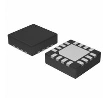
ON Semiconductor NLSF3T126MNR2

Mfr.Part #:

NLSF3T126MNR2

Manufacturer:

Description:
IC BUS BUFFER TRI-ST QUAD 16QFN

RoHS Status:

RoHS

Datasheet:

Payment:

Payment

Delivery:

Delivery

Quick Request Quote

Do you want a lower wholesale price? Please send us an inquiry, and we will respond immediately.

Latest Posts

A switch solenoid converts electrical energy into mechanical movement by using a simple principle:...
Voltage controlled oscillator takes a voltage (like from a battery) and turns it into...
Types of computer cables: USB cables, HDMI cables, Ethernet cables, power cables,VGA and display
A potentiometer is like a dimmer switch for electronic devices - it controls the...
Security

Buy With Confidence

ISO 9001
ISO 9001
ISO 45001
ISO 45001
ISO 13485
ISO 13485
ISO 14001
ISO 14001
SMTA
ASA

Specifications

Product Details

Product Comparison

Mount
Surface Mount
Mounting Type

Mounting Type refers to the method by which an electronic component is attached to a printed circuit board (PCB) or other surface. Common mounting types include: * Through-hole: Component leads are inserted into holes in the PCB and soldered on the other side. * Surface-mount: Component is placed on the surface of the PCB and soldered in place. * Press-fit: Component is pressed into place on the PCB without soldering. * Socket: Component is inserted into a socket on the PCB, allowing for easy replacement. The mounting type is determined by factors such as the component's size, shape, and power requirements.

Surface Mount
Package / Case

Package / Case refers to the physical housing or enclosure that encapsulates an electronic component. It provides protection, facilitates handling, and enables electrical connections. The package type determines the component's size, shape, pin configuration, and mounting options. Common package types include DIP (dual in-line package), SOIC (small outline integrated circuit), and BGA (ball grid array). The package also influences the component's thermal and electrical performance.

16-VFQFN Exposed Pad
Number of Pins

Number of Pins: Indicates the number of electrical connections available on the component. These pins are used to connect the component to other components or circuits on a printed circuit board (PCB). The number of pins determines the functionality and connectivity options of the component. It is important to ensure that the component has the correct number of pins for the intended application.

16
Operating Temperature

Operating Temperature is the range of temperatures at which an electronic component can function properly. It is typically specified in degrees Celsius (°C) and indicates the minimum and maximum temperatures at which the component can operate without experiencing damage or degradation. Operating Temperature is an important parameter to consider when designing electronic circuits, as it ensures that the components will function reliably in the intended operating environment.

-40°C~85°C TA
Packaging
Tape & Reel (TR)
Published
2004
JESD-609 Code
e0
Part Status

Part Status is an electronic component parameter that indicates the availability and production status of a component. It is typically used to inform customers about the availability of a component, whether it is in production, end-of-life, or obsolete. Part Status can also provide information about any restrictions or limitations on the component's use, such as whether it is only available for certain applications or if it has been discontinued.

Obsolete
Moisture Sensitivity Level (MSL)

Moisture Sensitivity Level (MSL) is a measure of the susceptibility of a surface mount electronic component to moisture-induced damage during soldering. It is classified into six levels, from 1 (least sensitive) to 6 (most sensitive). MSL is determined by the materials used in the component's construction, including the solderability of its terminals and the presence of moisture-absorbing materials. Components with higher MSL ratings require more stringent handling and storage conditions to prevent moisture absorption and subsequent damage during soldering.

1 (Unlimited)
Number of Terminations
16
Subcategory
Bus Driver/Transceivers
Packing Method
TAPE AND REEL
Max Power Dissipation
500mW
Technology

Technology, in the context of electronic components, refers to the specific manufacturing process and materials used to create the component. It encompasses the semiconductor fabrication techniques, such as the type of transistor used (e.g., MOSFET, BJT), the gate oxide thickness, and the interconnect materials. Technology also includes the packaging type, such as surface mount or through-hole, and the leadframe or substrate material. The technology used impacts the component's performance characteristics, such as speed, power consumption, and reliability.

CMOS
Voltage - Supply
2V~5.5V
Terminal Position
QUAD
Terminal Form
NO LEAD
Peak Reflow Temperature (Cel)
235
Number of Functions
4
Supply Voltage

Supply Voltage is the voltage required to power an electronic component. It is typically measured in volts (V) and is specified in the component's datasheet. The supply voltage must be within the specified range for the component to function properly. If the supply voltage is too low, the component may not function at all. If the supply voltage is too high, the component may be damaged.

3.3V
Terminal Pitch
0.5mm
Reach Compliance Code
not_compliant
Reflow Temperature-Max (s)
NOT SPECIFIED
Base Part Number
LSF3T126
Pin Count
16
Qualification Status
Not Qualified
Output Type

Output type refers to the type of signal or power that an electronic component can produce. It can be analog or digital, AC or DC, and can vary in voltage, current, or power levels. The output type is determined by the component's design and is crucial for matching it with other components in a circuit. Understanding the output type ensures proper signal processing, power delivery, and overall system functionality.

3-State
Polarity

Polarity refers to the direction of current flow through an electronic component. It is typically indicated by a plus (+) or minus (-) sign on the component's body. Components with polarity must be connected correctly in a circuit to function properly. For example, a diode will only allow current to flow in one direction, from the positive terminal to the negative terminal. If a diode is connected backwards, it will not conduct current.

Non-Inverting
Supply Voltage-Max (Vsup)
5.5V
Power Supplies
2.5/5V
Supply Voltage-Min (Vsup)
2V
Load Capacitance

Load Capacitance (CL) is a parameter that specifies the maximum capacitance that can be connected to the output of an electronic component without affecting its performance. It is typically measured in picofarads (pF) or nanofarads (nF). A high load capacitance can cause the output voltage to drop or the output current to increase, which can lead to instability or damage to the component.

50pF
Number of Ports

Number of Ports refers to the number of electrical connections or terminals available on an electronic component. It indicates the number of external devices or signals that can be connected to the component. For example, a transistor may have three ports (emitter, base, and collector), while a resistor has two ports (terminals). The number of ports determines the functionality and connectivity options of the component within a circuit.

2
Propagation Delay
11.5 ns
Family
3T
Logic Function
Buffer, Inverting
Current - Output High, Low
8mA 8mA
Logic Type

Logic Type refers to the type of logic implemented by an electronic component, such as a logic gate or flip-flop.

Buffer, Non-Inverting
Number of Bits per Element

Number of Bits Per Element (NBE) specifies the number of bits used to represent each element in a digital signal. It determines the resolution and precision of the signal. A higher NBE results in a more accurate representation of the signal, but also increases the data size and processing requirements. NBE is commonly used in digital-to-analog converters (DACs), analog-to-digital converters (ADCs), and other digital signal processing systems.

1
Control Type
ENABLE HIGH
Number of Input Lines
4
Number of Output Lines
3
RoHS Status
Non-RoHS Compliant
Lead Free
Contains Lead
Description
The NLSF3T126 is a high-speed CMOS quad bus buffer fabricated with silicon gate CMOS technology. It achieves non-inverting high-speed operation similar to equivalent Bipolar Schottky TTL while maintaining CMOS low power dissipation. The NLSF3T126 requires the 3-state control input (OE) to be set low to place the output into high impedance. The T126 inputs are compatible with TTL levels. This device can be used as a level converter for interfacing 3.3 V to 5.0 V, because it has full 5.0 V CMOS level output swings.

Features
TTL-Compatible Inputs: V-0.8 V, V-20 V
High Speed: tpp = 3.8 ns (Typ) at Vcc = 5 V
Low Power Dissipation: Icc 4.0 μA (Max) at Vcc = 5 V
Power Down Protection Provided on Inputs
Balanced Propagation Delays
Designed for 2.0 V to 5.5 V Operating Range
Low Noise: Voup = 0.8 V (Max)
Pin and Function Compatible with Other Logic Families
Latchup Performance Exceeds 300 mA
Chip Complexity: 72 FETs or 18 Equivalent Gates
Pb-Free Package is Available

Applications
Bus Buffering
Level Conversion
High-Speed Data Transmission
Interface between 3.3 V and 5.0 V Systems
No Product Comparison

Recommended Offers

Cypress Semiconductor Corp
MB90F543GSPF-GS-BI24
Microchip Technology
PIC16C662-10E/P
Melexis Technologies NV
MLX81108KDC-CAE-000-SP
Maxim Integrated
MAX3079EEPD+
Microchip Technology
ATMEGA8L-8PU
Microchip Technology
ATMEGA16U2-AU
Microchip Technology
DSPIC33EP128GP504-I/ML
Microchip Technology
ATSAM3U1CB-AU
Microchip Technology
PIC16F913-I/SO
Microchip Technology
PIC32MX130F064B-I/SS
Microchip Technology
PIC16F1788-I/SO
Microchip Technology
DSPIC33EP64MC204-I/PT