Factory Lead Time
6 Weeks
Mounting Type
Mounting Type refers to the method by which an electronic component is attached to a printed circuit board (PCB) or other surface. Common mounting types include:
* Through-hole: Component leads are inserted into holes in the PCB and soldered on the other side.
* Surface-mount: Component is placed on the surface of the PCB and soldered in place.
* Press-fit: Component is pressed into place on the PCB without soldering.
* Socket: Component is inserted into a socket on the PCB, allowing for easy replacement.
The mounting type is determined by factors such as the component's size, shape, and power requirements.
Surface Mount
Package / Case
Package / Case refers to the physical housing or enclosure that encapsulates an electronic component. It provides protection, facilitates handling, and enables electrical connections. The package type determines the component's size, shape, pin configuration, and mounting options. Common package types include DIP (dual in-line package), SOIC (small outline integrated circuit), and BGA (ball grid array). The package also influences the component's thermal and electrical performance.
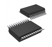
24-SSOP (0.154, 3.90mm Width)
Operating Temperature
Operating Temperature is the range of temperatures at which an electronic component can function properly. It is typically specified in degrees Celsius (°C) and indicates the minimum and maximum temperatures at which the component can operate without experiencing damage or degradation. Operating Temperature is an important parameter to consider when designing electronic circuits, as it ensures that the components will function reliably in the intended operating environment.
-40°C~85°C TA
Packaging
Tape & Reel (TR)
Series
Series, in the context of electronic components, refers to the arrangement of components in a circuit. When components are connected in series, they form a single path for current to flow through. The total resistance of a series circuit is the sum of the individual resistances of each component. Series connections are often used to control the flow of current in a circuit, as the total resistance can be adjusted by changing the number or type of components in the series.
C8051F82x
Part Status
Part Status is an electronic component parameter that indicates the availability and production status of a component. It is typically used to inform customers about the availability of a component, whether it is in production, end-of-life, or obsolete. Part Status can also provide information about any restrictions or limitations on the component's use, such as whether it is only available for certain applications or if it has been discontinued.
Not For New Designs
Moisture Sensitivity Level (MSL)
Moisture Sensitivity Level (MSL) is a measure of the susceptibility of a surface mount electronic component to moisture-induced damage during soldering. It is classified into six levels, from 1 (least sensitive) to 6 (most sensitive). MSL is determined by the materials used in the component's construction, including the solderability of its terminals and the presence of moisture-absorbing materials. Components with higher MSL ratings require more stringent handling and storage conditions to prevent moisture absorption and subsequent damage during soldering.
3 (168 Hours)
Frequency
Frequency, in the context of electronic components, refers to the rate at which an alternating current or voltage changes direction per second. It is measured in Hertz (Hz), which represents one cycle per second. Frequency is a crucial parameter for various electronic components, such as capacitors, inductors, and resonators. It determines the component's ability to store or release energy, filter signals, and resonate at specific frequencies. Understanding the frequency characteristics of electronic components is essential for designing and optimizing electronic circuits.
25MHz
Operating Supply Voltage
3V
Number of Channels
Number of Channels refers to the number of independent signal paths within an electronic component. It indicates how many separate signals can be processed or transmitted simultaneously. For example, an audio amplifier with two channels can amplify two separate audio signals, while a multi-channel data converter can convert multiple analog signals into digital data. The number of channels is a crucial parameter for determining the component's functionality and application.
3
Interface
In electronics, an interface refers to the connection point or boundary between two or more electronic systems or devices. It defines the physical, electrical, and logical characteristics that enable communication and data exchange between them.
An interface specifies the protocols, pinouts, voltage levels, data formats, and other parameters necessary for the systems to interact seamlessly. It ensures compatibility and interoperability between different components or devices, allowing them to exchange information and perform their intended functions.
2-Wire, I2C, SMBus, SPI, UART, USART
Voltage - Supply (Vcc/Vdd)
1.8V~3.6V
Core Processor
Core Processor refers to the central processing unit (CPU) of an electronic device. It is the brain of the device, responsible for executing instructions, processing data, and managing the overall operation of the system. The core processor's speed, number of cores, and architecture determine the device's performance and capabilities.
8051
Peripherals
POR, PWM, WDT
Program Memory Type
FLASH
Core Size
Core Size refers to the physical dimensions of the magnetic core used in an electronic component, such as an inductor or transformer. It is typically expressed in terms of its length, width, and height, or as a diameter and height for cylindrical cores. The core size determines the inductance, current-carrying capacity, and other electrical characteristics of the component. Larger core sizes generally result in higher inductance and current-handling capabilities.
8-Bit
Program Memory Size
8KB 8K x 8
Connectivity
Connectivity refers to the number of terminals or pins on an electronic component that allow it to connect to other components in a circuit. It determines the component's ability to interact and exchange signals with other elements in the system. Higher connectivity indicates more connection points, enabling the component to perform complex functions and integrate with various circuits.
SMBus (2-Wire/I2C), SPI, UART/USART
Data Bus Width
Data Bus Width refers to the number of bits that can be transmitted simultaneously on a data bus. It determines the amount of data that can be transferred between components in a single operation. A wider data bus allows for faster data transfer rates and higher system performance. Common data bus widths include 8, 16, 32, and 64 bits, with wider buses typically found in high-performance systems.
8b
RoHS Status
RoHS Compliant
C8051F820-GUR Overview
A 24-SSOP (0.154, 3.90mm Width) package is included. In total, it has 17 inputs and outputs. This Microcontroller is mounted using the Surface Mount mounting type. Powered by the 8-Bit core, it offers a wide range of capabilities. The type of memory that the program uses is FLASH. The temperature range of this Microcontroller is within the range of -40°C~85°C TA. C8051F82x series components belong to this electrical component. Its program memory size is 8KB 8K x 8. There is a 8051 Core Processor inside MCU that provides this device with its power. 8kB memory size belongs to the part. A good performance can be achieved at a frequency of 25MHz, as long as it is operated at a low power consumption.
C8051F820-GUR Features
24-SSOP (0.154, 3.90mm Width) package
Mounting type of Surface Mount
C8051F820-GUR Applications
There are a lot of Silicon Labs
C8051F820-GUR Microcontroller applications.
Calculator
Kindle
Christmas lights
3D printers
Washing machine
Microwave ovens
Home appliances
Home video and audio
Entertainment products
Digital cameras
C8051F820-GUR More Descriptions
MCU 8-bit C8051F8xx 8051 CISC 8KB Flash 3V 24-Pin QSOP T/R
C8051F80x/1x/2x/3x Capacitive Touch Sense MCUs,8kB Flash, QSOP24Silicon Labs SCT
8-bit Microcontrollers - MCU 8kB/512B RAM, QSOP24
MCU Core: 8051; MHz: 25; Flash (kb): 8 kB; RAM (kb): 0.5; Digital Port I/O: 17; Communications: UART, I2C, SPI; Timers (16-bit): 3; PCA Channels: 3; Debug Interface: C2; Package: 24 QSOP; Dev Kit: C8051F800DK; VREF: false; Automotive: false; Cap Sense: true; Comparators: 1