Factory Lead Time
23 Weeks
Mounting Type
Mounting Type refers to the method by which an electronic component is attached to a printed circuit board (PCB) or other surface. Common mounting types include:
* Through-hole: Component leads are inserted into holes in the PCB and soldered on the other side.
* Surface-mount: Component is placed on the surface of the PCB and soldered in place.
* Press-fit: Component is pressed into place on the PCB without soldering.
* Socket: Component is inserted into a socket on the PCB, allowing for easy replacement.
The mounting type is determined by factors such as the component's size, shape, and power requirements.
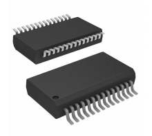
Surface Mount
Package / Case
Package / Case refers to the physical housing or enclosure that encapsulates an electronic component. It provides protection, facilitates handling, and enables electrical connections. The package type determines the component's size, shape, pin configuration, and mounting options. Common package types include DIP (dual in-line package), SOIC (small outline integrated circuit), and BGA (ball grid array). The package also influences the component's thermal and electrical performance.
28-SSOP (0.209, 5.30mm Width)
Number of Pins
Number of Pins: Indicates the number of electrical connections available on the component. These pins are used to connect the component to other components or circuits on a printed circuit board (PCB). The number of pins determines the functionality and connectivity options of the component. It is important to ensure that the component has the correct number of pins for the intended application.
28
Supplier Device Package
28-SSOP
Operating Temperature
Operating Temperature is the range of temperatures at which an electronic component can function properly. It is typically specified in degrees Celsius (°C) and indicates the minimum and maximum temperatures at which the component can operate without experiencing damage or degradation. Operating Temperature is an important parameter to consider when designing electronic circuits, as it ensures that the components will function reliably in the intended operating environment.
-40°C~125°C TA
Series
Series, in the context of electronic components, refers to the arrangement of components in a circuit. When components are connected in series, they form a single path for current to flow through. The total resistance of a series circuit is the sum of the individual resistances of each component. Series connections are often used to control the flow of current in a circuit, as the total resistance can be adjusted by changing the number or type of components in the series.
Automotive, AEC-Q100, dsPIC™ 33EP
Part Status
Part Status is an electronic component parameter that indicates the availability and production status of a component. It is typically used to inform customers about the availability of a component, whether it is in production, end-of-life, or obsolete. Part Status can also provide information about any restrictions or limitations on the component's use, such as whether it is only available for certain applications or if it has been discontinued.
Active
Moisture Sensitivity Level (MSL)
Moisture Sensitivity Level (MSL) is a measure of the susceptibility of a surface mount electronic component to moisture-induced damage during soldering. It is classified into six levels, from 1 (least sensitive) to 6 (most sensitive). MSL is determined by the materials used in the component's construction, including the solderability of its terminals and the presence of moisture-absorbing materials. Components with higher MSL ratings require more stringent handling and storage conditions to prevent moisture absorption and subsequent damage during soldering.
1 (Unlimited)
Max Operating Temperature
125°C
Min Operating Temperature
-40°C
Frequency
Frequency, in the context of electronic components, refers to the rate at which an alternating current or voltage changes direction per second. It is measured in Hertz (Hz), which represents one cycle per second. Frequency is a crucial parameter for various electronic components, such as capacitors, inductors, and resonators. It determines the component's ability to store or release energy, filter signals, and resonate at specific frequencies. Understanding the frequency characteristics of electronic components is essential for designing and optimizing electronic circuits.
60MHz
Base Part Number
DSPIC33EP64MC202
Operating Supply Voltage
3.3V
Interface
In electronics, an interface refers to the connection point or boundary between two or more electronic systems or devices. It defines the physical, electrical, and logical characteristics that enable communication and data exchange between them.
An interface specifies the protocols, pinouts, voltage levels, data formats, and other parameters necessary for the systems to interact seamlessly. It ensures compatibility and interoperability between different components or devices, allowing them to exchange information and perform their intended functions.
I2C, IrDA, LIN, SPI, UART, USART
Speed
Speed, in the context of electronic components, refers to the rate at which the component can process or transmit data. It is typically measured in units of bits per second (bps), megabits per second (Mbps), or gigabits per second (Gbps). The speed of a component is determined by its internal design and the technology used to manufacture it. Faster components can handle more data in a given amount of time, which can improve the overall performance of a system.
60 MIPs
Memory Type
Memory Type refers to the type of memory technology used in an electronic device. It indicates the specific design and architecture of the memory, such as DRAM (Dynamic Random Access Memory), SRAM (Static Random Access Memory), ROM (Read-Only Memory), EEPROM (Electrically Erasable Programmable Read-Only Memory), or Flash memory. Each memory type has unique characteristics, including speed, capacity, volatility, and cost, which determine its suitability for different applications.
FLASH
Voltage - Supply (Vcc/Vdd)
3V~3.6V
Core Processor
Core Processor refers to the central processing unit (CPU) of an electronic device. It is the brain of the device, responsible for executing instructions, processing data, and managing the overall operation of the system. The core processor's speed, number of cores, and architecture determine the device's performance and capabilities.
dsPIC
Peripherals
Brown-out Detect/Reset, DMA, Motor Control PWM, POR, PWM, WDT
Program Memory Type
FLASH
Core Size
Core Size refers to the physical dimensions of the magnetic core used in an electronic component, such as an inductor or transformer. It is typically expressed in terms of its length, width, and height, or as a diameter and height for cylindrical cores. The core size determines the inductance, current-carrying capacity, and other electrical characteristics of the component. Larger core sizes generally result in higher inductance and current-handling capabilities.
16-Bit
Program Memory Size
64KB 22K x 24
Connectivity
Connectivity refers to the number of terminals or pins on an electronic component that allow it to connect to other components in a circuit. It determines the component's ability to interact and exchange signals with other elements in the system. Higher connectivity indicates more connection points, enabling the component to perform complex functions and integrate with various circuits.
I2C, IrDA, LINbus, QEI, SPI, UART/USART
Data Converter
A/D 6x10b/12b
Data Bus Width
Data Bus Width refers to the number of bits that can be transmitted simultaneously on a data bus. It determines the amount of data that can be transferred between components in a single operation. A wider data bus allows for faster data transfer rates and higher system performance. Common data bus widths include 8, 16, 32, and 64 bits, with wider buses typically found in high-performance systems.
16b
Number of Timers/Counters
5
Number of Programmable I/O
28
RoHS Status
ROHS3 Compliant
Description
The dsPIC33EPXXXGP50X, dsPIC33EPXXXMC20X/50X, and PIC24EPXXXGP/MC20X are 16-bit microcontrollers and digital signal controllers with high-speed PWM, op amps, and advanced analog features. They operate at 3.0V to 3.6V, with temperature ranges from -40°C to 85°C, -40°C to 125°C, and -40°C to 150°C, and clock speeds up to 70 MIPS, 60 MIPS, and 40 MIPS, respectively.
Features
16-bit dsPIC33E/PIC24E CPU with code-efficient architecture
Two 40-bit wide accumulators
Single-cycle MAC/MPY with dual data fetch
Single-cycle, mixed-sign MUL plus hardware divide
32-bit multiply support
1.0% internal oscillator
Programmable PLLs and oscillator clock sources
Fail-safe clock monitor (FSCM)
Independent watchdog timer (WDT)
Fast wake-up and start-up
Low-power management modes (Sleep, Idle, Doze)
Integrated power-on reset and brown-out reset
0.6 mA/MHz dynamic current (typical)
30 μA IPD current (typical)
Up to three PWM pairs with independent timing
Dead time for rising and falling edges
7.14 ns PWM resolution
PWM support for DC/DC, AC/DC, inverters, PFC, lighting, BLDC, PMSM, ACIM, SRM
Programmable fault inputs
Flexible trigger configurations for ADC conversions
ADC module configurable as 10-bit, 1.1 Msps with four S&H or 12-bit, 500 kaps with one S&H
Six analog inputs on 28-pin devices and up to 16 analog inputs on 64-pin devices
Flexible and independent ADC trigger sources
Up to three op amp/comparators with direct connection to the ADC module
Additional dedicated comparator
Programmable references with 32 voltage points
Charge Time Measurement Unit (CTMU) for mTouch® capacitive touch sensing
High-resolution time measurement (1 ns)
On-chip temperature measurement
12 general purpose timers
Four output compare (OC) modules, configurable as timers/counters
PTG module with two configurable timers/counters
32-bit quadrature encoder interface (QEI) module, configurable as a timer/counter
Four input capture (IC) modules
Peripheral Pin Select (PPS) to allow function remap
Peripheral Trigger Generator (PTG) for scheduling complex sequences
Two UART modules (17.5 Mbps) with support for LIN/J2602 protocols and IrDA
Two four-wire SPI modules (15 Mbps)
ECAN™ module (1 Mbaud) CAN 2.0B support
Two 12C modules (up to 1 Mbaud) with SMBus support
PPS to allow function remap
Programmable cyclic redundancy check (CRC)
4-channel DMA with user-selectable priority arbitration
UART, SPI, ADC, ECAN, IC, OC, and timers
Sink/source 12 mA or 6 mA, pin-specific for standard VOH/VOL, up to 22 or 14 mA, respectively, for non-standard VOH1
5V tolerant pins
Peripheral Pin Select (PPS) to allow digital function remapping
Selectable open-drain, pull-ups, and pull-downs
Up to 5 mA overvoltage clamp current
Change notification interrupts on all I/O pins
AEC-Q100 REVG (Grade 1, -40°C to 125°C)
AEC-Q100 REVG (Grade 0, -40°C to 150°C)
Class B safety library, IEC 60730
In-circuit and in-application programming
Two program and two complex data breakpoints
IEEE 1149.2 compatible (JTAG) boundary scan
Trace and run-time watch
Applications
Automotive
Industrial
Medical
Consumer
Aerospace and defense