Mounting Type
Mounting Type refers to the method by which an electronic component is attached to a printed circuit board (PCB) or other surface. Common mounting types include:
* Through-hole: Component leads are inserted into holes in the PCB and soldered on the other side.
* Surface-mount: Component is placed on the surface of the PCB and soldered in place.
* Press-fit: Component is pressed into place on the PCB without soldering.
* Socket: Component is inserted into a socket on the PCB, allowing for easy replacement.
The mounting type is determined by factors such as the component's size, shape, and power requirements.
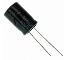
Through Hole
Package / Case
Package / Case refers to the physical housing or enclosure that encapsulates an electronic component. It provides protection, facilitates handling, and enables electrical connections. The package type determines the component's size, shape, pin configuration, and mounting options. Common package types include DIP (dual in-line package), SOIC (small outline integrated circuit), and BGA (ball grid array). The package also influences the component's thermal and electrical performance.
Radial, Can
Number of Pins
Number of Pins: Indicates the number of electrical connections available on the component. These pins are used to connect the component to other components or circuits on a printed circuit board (PCB). The number of pins determines the functionality and connectivity options of the component. It is important to ensure that the component has the correct number of pins for the intended application.
2
Dielectric Material
Aluminium
Operating Temperature
Operating Temperature is the range of temperatures at which an electronic component can function properly. It is typically specified in degrees Celsius (°C) and indicates the minimum and maximum temperatures at which the component can operate without experiencing damage or degradation. Operating Temperature is an important parameter to consider when designing electronic circuits, as it ensures that the components will function reliably in the intended operating environment.
-25°C~85°C
Series
Series, in the context of electronic components, refers to the arrangement of components in a circuit. When components are connected in series, they form a single path for current to flow through. The total resistance of a series circuit is the sum of the individual resistances of each component. Series connections are often used to control the flow of current in a circuit, as the total resistance can be adjusted by changing the number or type of components in the series.
SK
Size / Dimension
0.512Dia 13.00mm
Tolerance
Tolerance in electronic components refers to the allowable deviation from the specified value. It indicates the range within which the actual value of the component can vary while still meeting the manufacturer's specifications. Tolerance is typically expressed as a percentage of the nominal value, such as ±5% or ±10%. A lower tolerance indicates a tighter range of acceptable values, resulting in more precise and consistent performance.
±20%
Part Status
Part Status is an electronic component parameter that indicates the availability and production status of a component. It is typically used to inform customers about the availability of a component, whether it is in production, end-of-life, or obsolete. Part Status can also provide information about any restrictions or limitations on the component's use, such as whether it is only available for certain applications or if it has been discontinued.
Active
Moisture Sensitivity Level (MSL)
Moisture Sensitivity Level (MSL) is a measure of the susceptibility of a surface mount electronic component to moisture-induced damage during soldering. It is classified into six levels, from 1 (least sensitive) to 6 (most sensitive). MSL is determined by the materials used in the component's construction, including the solderability of its terminals and the presence of moisture-absorbing materials. Components with higher MSL ratings require more stringent handling and storage conditions to prevent moisture absorption and subsequent damage during soldering.
1 (Unlimited)
Termination
Termination refers to the electrical characteristics of a component or circuit at its input or output terminals. It describes how the component or circuit interacts with external signals or devices. Termination can involve matching impedance, providing voltage or current regulation, or filtering unwanted signals. Proper termination ensures efficient signal transfer, minimizes reflections, and prevents damage to components. It is crucial for maintaining signal integrity and optimizing circuit performance.
Radial
Applications
General Purpose
Capacitance
Capacitance is the ability of a component to store electrical charge. It is measured in farads (F). A capacitor is a passive electronic component that consists of two conductors separated by an insulator. When a voltage is applied across the capacitor, charge builds up on the conductors. The amount of charge that can be stored depends on the capacitance of the capacitor. Capacitors are used in a variety of electronic circuits, including filters, timing circuits, and energy storage devices.
22μF
Capacitor Type
ALUMINUM ELECTROLYTIC CAPACITOR
Lead Length
Lead length refers to the distance between the body of an electronic component and the point where its leads or terminals emerge. It is a crucial parameter that affects the component's performance, reliability, and ease of assembly. Lead length influences factors such as inductance, capacitance, and heat dissipation. Longer leads can increase inductance and capacitance, which may impact signal integrity and circuit performance. They can also affect heat dissipation, as longer leads provide a larger surface area for heat transfer. Optimal lead length is determined based on the component's intended application and the desired electrical and thermal characteristics.
15mm
ESR (Equivalent Series Resistance)
9.05Ohm @ 120Hz
Lead Spacing
Lead spacing refers to the distance between the centers of two adjacent leads on an electronic component. It is typically measured in millimeters (mm) or inches (in). Lead spacing is an important parameter to consider when designing printed circuit boards (PCBs), as it determines the size and layout of the board. Proper lead spacing ensures that the component can be properly mounted and soldered onto the PCB, and that there is sufficient clearance between the leads to prevent short circuits.
0.197 5.00mm
Lifetime @ Temp
2000 Hrs @ 85°C
Leakage Current
Leakage current is the small amount of current that flows through an electronic component when it is not supposed to. It is typically measured in nanoamperes (nA) or picoamperes (pA). Leakage current can be caused by a number of factors, including the type of semiconductor material used, the manufacturing process, and the operating temperature. Leakage current can be a problem in electronic circuits because it can lead to increased power consumption and reduced battery life.
0.165mA
Ripple Current
Ripple current is the alternating current (AC) component of the current flowing through a capacitor. It is caused by the charging and discharging of the capacitor as the AC voltage applied to it changes. The ripple current can cause the capacitor to heat up and can also lead to premature failure. The maximum ripple current that a capacitor can handle is specified in its datasheet.
130mA
Polarization
Polarization in electronic components refers to the orientation of the electric field within the component. It is a measure of the component's ability to store electrical energy. A polarized component has a positive and a negative terminal, and the electric field is oriented from the positive to the negative terminal. When a polarized component is connected to a voltage source, the electric field is established and the component stores electrical energy.
Polar
Ripple Current @ Low Frequency
130mA @ 120Hz
Ripple Current @ High Frequency
182mA @ 1kHz
Dissipation Factor
Dissipation Factor (DF) is a measure of the energy lost in a capacitor due to its internal resistance. It is expressed as a percentage of the total energy stored in the capacitor. A low DF indicates a high-quality capacitor with low energy loss, while a high DF indicates a low-quality capacitor with significant energy loss. DF is important in applications where energy efficiency is crucial, such as power factor correction and filtering circuits.
15 %
Height
Height, in the context of electronic components, refers to the vertical dimension of the component. It is typically measured in millimeters (mm) or inches (in). Height is an important parameter to consider when designing and assembling electronic circuits, as it affects the overall size and form factor of the device. Components with a smaller height are often preferred for applications where space is limited, such as in portable devices or embedded systems.
21mm
Height Seated (Max)
0.906 23.00mm
RoHS Status
ROHS3 Compliant
SK220M250ST Overview
As far as the ripple current is concerned, it is 182mA @ 1kHz at full charge.The ESR (Equivalent Series Resistance) of 9.05Ohm @ 120Hz needs to be provided to fully play its function.As far as the ripple current is concerned, it is 130mA @ 120Hz at the lowest charge.The height seated (Max) should be kept below 0.906 23.00mm.It operates from a 15 % dissipation factor.This capacitor operates from a voltage - Rated DC of 250V.The operating temperature should be maintained at -25°C~85°C for high efficiency.
SK220M250ST Features
the ripple current is 182mA @ 1kHz.
the ripple current is 130mA @ 120Hz.
a dissipation factor of 15 %
voltage - Rated DC of 250V
an operating temperature of -25°C~85°C
SK220M250ST Applications
There are a lot of Cornell Dubilier Electronics (CDE)
SK220M250ST applications of aluminum electrolytic capacitors.
Power supplies
Computer motherboards
Uninterruptible power supplies
Frequency converters
Computer
Telecommunication
Industrial systems
Smoothing and filtering applications
Standard and switched mode power supplies
Energy storage in pulse systems
SK220M250ST More Descriptions
Capacitor, Al Electrolytic, 250 WVDC, /-20, Radial Leaded, 15% at 120 Hz, 25 C
Aluminum Electrolytic Capacitors - Radial Leaded 22uF 250V
Aluminum Electrolytic Capacitor 22Uf, 250V, 20%, Radial; Capacitance:22Μf; Voltage(Dc):250V; Capacitance Tolerance:± 20%; Capacitor Terminals:Pc Pin; Lifetime @ Temperature:2000 Hours @ 85°C; Polarity:Polar; Lead Spacing:5Mm Rohs Compliant: Yes |Cornell Dubilier SK220M250ST