Factory Lead Time
18 Weeks
Mounting Type
Mounting Type refers to the method by which an electronic component is attached to a printed circuit board (PCB) or other surface. Common mounting types include:
* Through-hole: Component leads are inserted into holes in the PCB and soldered on the other side.
* Surface-mount: Component is placed on the surface of the PCB and soldered in place.
* Press-fit: Component is pressed into place on the PCB without soldering.
* Socket: Component is inserted into a socket on the PCB, allowing for easy replacement.
The mounting type is determined by factors such as the component's size, shape, and power requirements.
Surface Mount
Package / Case
Package / Case refers to the physical housing or enclosure that encapsulates an electronic component. It provides protection, facilitates handling, and enables electrical connections. The package type determines the component's size, shape, pin configuration, and mounting options. Common package types include DIP (dual in-line package), SOIC (small outline integrated circuit), and BGA (ball grid array). The package also influences the component's thermal and electrical performance.
Nonstandard
Terminal Shape
ONE SURFACE
Number of Pins
Number of Pins: Indicates the number of electrical connections available on the component. These pins are used to connect the component to other components or circuits on a printed circuit board (PCB). The number of pins determines the functionality and connectivity options of the component. It is important to ensure that the component has the correct number of pins for the intended application.
2
Material
In electronic components, "Material" refers to the substance or composition used to construct the component. It determines the electrical, mechanical, and thermal properties of the component.
Resin
Shape/Size Description
RECTANGULAR PACKAGE
Operating Temperature
Operating Temperature is the range of temperatures at which an electronic component can function properly. It is typically specified in degrees Celsius (°C) and indicates the minimum and maximum temperatures at which the component can operate without experiencing damage or degradation. Operating Temperature is an important parameter to consider when designing electronic circuits, as it ensures that the components will function reliably in the intended operating environment.
-40°C~125°C
Series
Series, in the context of electronic components, refers to the arrangement of components in a circuit. When components are connected in series, they form a single path for current to flow through. The total resistance of a series circuit is the sum of the individual resistances of each component. Series connections are often used to control the flow of current in a circuit, as the total resistance can be adjusted by changing the number or type of components in the series.
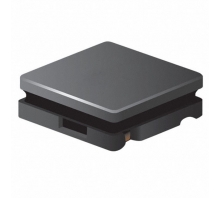
SRN3010
Size / Dimension
0.118Lx0.118W 3.00mmx3.00mm
Tolerance
Tolerance in electronic components refers to the allowable deviation from the specified value. It indicates the range within which the actual value of the component can vary while still meeting the manufacturer's specifications. Tolerance is typically expressed as a percentage of the nominal value, such as ±5% or ±10%. A lower tolerance indicates a tighter range of acceptable values, resulting in more precise and consistent performance.
±20%
Part Status
Part Status is an electronic component parameter that indicates the availability and production status of a component. It is typically used to inform customers about the availability of a component, whether it is in production, end-of-life, or obsolete. Part Status can also provide information about any restrictions or limitations on the component's use, such as whether it is only available for certain applications or if it has been discontinued.
Active
Moisture Sensitivity Level (MSL)
Moisture Sensitivity Level (MSL) is a measure of the susceptibility of a surface mount electronic component to moisture-induced damage during soldering. It is classified into six levels, from 1 (least sensitive) to 6 (most sensitive). MSL is determined by the materials used in the component's construction, including the solderability of its terminals and the presence of moisture-absorbing materials. Components with higher MSL ratings require more stringent handling and storage conditions to prevent moisture absorption and subsequent damage during soldering.
1 (Unlimited)
Termination
Termination refers to the electrical characteristics of a component or circuit at its input or output terminals. It describes how the component or circuit interacts with external signals or devices. Termination can involve matching impedance, providing voltage or current regulation, or filtering unwanted signals. Proper termination ensures efficient signal transfer, minimizes reflections, and prevents damage to components. It is crucial for maintaining signal integrity and optimizing circuit performance.
SMD/SMT
Terminal Finish
Tin/Silver/Copper (Sn/Ag/Cu)
Packing Method
TR, 7 Inch
Current Rating
Current Rating is the maximum amount of current that an electronic component can safely handle without overheating or failing. It is typically expressed in amperes (A) or milliamperes (mA). Exceeding the current rating can damage the component and potentially create a safety hazard. The current rating is determined by the physical characteristics of the component, such as its size, material, and construction.
900mA
Inductance
Inductance is a property of an electrical conductor that opposes changes in current flow. It is measured in henrys (H) and is represented by the symbol L. Inductance is caused by the magnetic field generated by the current flowing through the conductor. When the current changes, the magnetic field also changes, which induces an electromotive force (EMF) in the conductor. This EMF opposes the change in current flow.
10μH
Test Frequency
Test Frequency refers to the frequency at which an electronic component is tested to ensure it meets its specified performance parameters. It is typically expressed in Hertz (Hz) and represents the frequency range over which the component is tested. This parameter is important for ensuring the component's reliability and performance under different operating conditions.
100kHz
DC Resistance (DCR)
DC Resistance (DCR) is a measure of the resistance of an electrical component to the flow of direct current (DC). It is typically measured in ohms (Ω) and is an important parameter for understanding the behavior of electrical components. DCR can affect the efficiency, power consumption, and overall performance of a circuit. It is often used to characterize inductors, capacitors, and other components that have a resistive element.
420mOhm Max
Frequency - Self Resonant
40MHz
Inductor Application
POWER INDUCTOR
Terminal Placement
DUAL ENDED
Q @ Freq
Q @ Freq is a parameter that describes the quality factor of an electronic component at a specific frequency. It is a measure of the component's ability to store and release energy, and is typically expressed as a ratio of the component's reactance to its resistance. A higher Q factor indicates a more efficient component, with less energy loss. Q @ Freq is important for understanding the performance of electronic circuits, as it can affect factors such as bandwidth, selectivity, and stability.
11 @ 2.52MHz
Quality Factor-Min (at L-nom)
11
Current - Saturation
600mA
Height
Height, in the context of electronic components, refers to the vertical dimension of the component. It is typically measured in millimeters (mm) or inches (in). Height is an important parameter to consider when designing and assembling electronic circuits, as it affects the overall size and form factor of the device. Components with a smaller height are often preferred for applications where space is limited, such as in portable devices or embedded systems.
1mm
Height Seated (Max)
0.039 1.00mm
RoHS Status
ROHS3 Compliant
The SRN3010-100M is FIXED IND 10UH 900MA 420 MOHM , it is part of SRN3010 series. they are designed to work as Fixed Inductors.SRN3010-100M with pin details manufactured by Bourns, Inc.. The SRN3010-100M is available in - Package,it is part of the electronic component Chips.that includes SRN3010 Series. they are designed to operate as Fixed Inductors.it is with Operating Temperature -40°C ~ 125°C.SRN3010-100M with original stock manufactured by Bourns, Inc.. The SRN3010-100M is available in - Package.Generally IC chips offer Mounting Style features such as SMD/SMT, Package Case of SRN3010-100Mis designed to work in Nonstandard, it's Operating Temperature is -40°C ~ 125°C.The SRN3010-100M is available in Nonstandard Package, is part of the Fixed Inductors and belong to Inductors, Coils, Chokes.SRN3010-100M with EDA / CAD Models manufactured by Bourns, Inc.. The SRN3010-100M is available in -Package, is part of the Inductors, Coils, Chokes.The SRN3010-100M is Fixed Inductors with package Nonstandard manufactured by Bourns, Inc.. The SRN3010-100M is available in - Package, is part of the FIXED IND 10UH 900MA 420 MOHM.
SRN3010-100M More Descriptions
Ind Power Semi-Shielded Wirewound 10uH 20% 100KHz Ferrite 900mA 1212 T/RAvnet Japan
Inductor, Semi-Shielded, Ind 10 uH, Tol 20%,Cur-Rtg 0.9 A, SMT,1212 | Bourns SRN3010-100M
Power Inductor (SMD), 10 uH, ± 20%, 900 mA, Semishielded, 600 mA, 3mm x 3mm x 1mm
Inductor, Semi-Shielded, 10Uh, 900Ma, 20%, Smd; Inductance:10Μh; Rms Current (Irms):900Ma; Inductor Construction:Semishielded; Saturation Current (Isat):600Ma; Product Range:Srn3010 Series; Power Inductor Case:3Mm X 3Mm X 1Mm Rohs Compliant: Yes |Bourns SRN3010-100M