Factory Lead Time
10 Weeks
Contact Material
Contact Material refers to the material used to make the electrical contacts in a component. It determines the electrical conductivity, durability, and resistance to corrosion and wear of the contacts. Common contact materials include copper, silver, gold, and alloys of these metals. The choice of contact material depends on the specific application and the required performance characteristics.
Beryllium Copper
Mounting Type
Mounting Type refers to the method by which an electronic component is attached to a printed circuit board (PCB) or other surface. Common mounting types include:
* Through-hole: Component leads are inserted into holes in the PCB and soldered on the other side.
* Surface-mount: Component is placed on the surface of the PCB and soldered in place.
* Press-fit: Component is pressed into place on the PCB without soldering.
* Socket: Component is inserted into a socket on the PCB, allowing for easy replacement.
The mounting type is determined by factors such as the component's size, shape, and power requirements.
Through Hole
Contact Shape
Contact Shape refers to the physical form of the electrical contacts within an electronic component. It describes the geometry and arrangement of the contacts, which can vary depending on the component's function and application. Common contact shapes include flat, round, pointed, and bifurcated (split) contacts. The shape of the contacts affects factors such as current-carrying capacity, contact resistance, and reliability.
Circular
Insulation Material
Liquid Crystal Polymer (LCP), Glass Filled
Operating Temperature
Operating Temperature is the range of temperatures at which an electronic component can function properly. It is typically specified in degrees Celsius (°C) and indicates the minimum and maximum temperatures at which the component can operate without experiencing damage or degradation. Operating Temperature is an important parameter to consider when designing electronic circuits, as it ensures that the components will function reliably in the intended operating environment.
-55°C~125°C
Series
Series, in the context of electronic components, refers to the arrangement of components in a circuit. When components are connected in series, they form a single path for current to flow through. The total resistance of a series circuit is the sum of the individual resistances of each component. Series connections are often used to control the flow of current in a circuit, as the total resistance can be adjusted by changing the number or type of components in the series.
833
Part Status
Part Status is an electronic component parameter that indicates the availability and production status of a component. It is typically used to inform customers about the availability of a component, whether it is in production, end-of-life, or obsolete. Part Status can also provide information about any restrictions or limitations on the component's use, such as whether it is only available for certain applications or if it has been discontinued.
Active
Moisture Sensitivity Level (MSL)
Moisture Sensitivity Level (MSL) is a measure of the susceptibility of a surface mount electronic component to moisture-induced damage during soldering. It is classified into six levels, from 1 (least sensitive) to 6 (most sensitive). MSL is determined by the materials used in the component's construction, including the solderability of its terminals and the presence of moisture-absorbing materials. Components with higher MSL ratings require more stringent handling and storage conditions to prevent moisture absorption and subsequent damage during soldering.
1 (Unlimited)
Termination
Termination refers to the electrical characteristics of a component or circuit at its input or output terminals. It describes how the component or circuit interacts with external signals or devices. Termination can involve matching impedance, providing voltage or current regulation, or filtering unwanted signals. Proper termination ensures efficient signal transfer, minimizes reflections, and prevents damage to components. It is crucial for maintaining signal integrity and optimizing circuit performance.
Solder
Connector Type
Connector Type refers to the physical interface used to connect an electronic component to other devices or systems. It specifies the shape, size, pin configuration, and mating mechanism of the connector. Common connector types include USB, HDMI, Ethernet, and power connectors. The choice of connector type depends on factors such as signal type, data rate, power requirements, and environmental conditions.
Socket
Number of Positions
Number of Positions, in the context of electronic components, refers to the number of distinct terminals or connection points available on the component. It indicates the number of individual electrical connections that can be made to the component. A higher number of positions typically allows for more complex functionality and versatility in circuit design.
14
Subcategory
Headers and Edge Type Connectors
Contact Finish - Mating
Gold
Contact Type
Contact Type refers to the physical construction and materials used in the electrical contacts of a component. It describes the type of connection made between two or more conductors.
Female Socket
Insulation Height
0.453 11.50mm
Style
Style in the context of electronic components refers to the physical form or design of the component. It encompasses various aspects such as the shape, size, mounting method, and packaging. The style of a component is crucial for determining its compatibility with specific applications and circuit board designs. It ensures proper fit, functionality, and ease of assembly. Common styles include through-hole, surface mount, axial, radial, and various specialized form factors tailored to specific applications.
Board to Board
Number of Positions Loaded
All
Reach Compliance Code
unknown
Pitch - Mating
0.079 2.00mm
Body Length or Diameter
0.551 inch
Row Spacing - Mating
0.079 (2.00mm)
Contact Length - Post
0.125 3.18mm
Contact Finish - Post
Tin
PCB Contact Pattern
RECTANGULAR
Contact Resistance
Contact resistance is the electrical resistance between two electrical contacts. It is caused by the imperfect contact between the two surfaces, which results in a small amount of resistance to the flow of current. Contact resistance can be a significant factor in the performance of electrical circuits, especially in high-power applications. It can cause power loss, heating, and even damage to components.
10mOhm
Insulation Resistance
Insulation Resistance is a measure of the resistance of an insulating material to the flow of electric current. It is typically measured in megaohms (MΩ) or gigohms (GΩ). A high insulation resistance indicates that the material is a good insulator, while a low insulation resistance indicates that the material is a poor insulator. Insulation resistance is important for preventing electrical leakage and ensuring the safe operation of electrical equipment.
10000000000Ohm
Mating Contact Pitch
0.079 inch
Polarization Key
POLARIZED HOUSING
Contact Finish Thickness - Mating
29.5μin 0.75μm
Material Flammability Rating
UL94 V-0
RoHS Status
ROHS3 Compliant
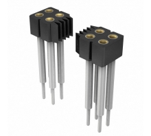
833-83-014-10-287101 Overview
Packaging is Socket.Through Hole is the mounting type.Packaging for the product is carried out via a Bulk case.As a product of the 833 Series, it can be found in this category.In this case, Through Hole mounts the part.The device is operating at -55°C~125°C Operating Temperature.
833-83-014-10-287101 Features
833 series
833-83-014-10-287101 Applications
There are a lot of Preci-Dip
833-83-014-10-287101 Rectangular Connectors applications.
Embedded systems
Datacom
Communication
Medical technology
Military Technology
Measuring & Control Technology
Instrumentation
Automotive Electronics
Telecommunications
Data Technology
833-83-014-10-287101 More Descriptions
CONN SOCKET 14POS 0.079 GOLD PCB