Mounting Type
Mounting Type refers to the method by which an electronic component is attached to a printed circuit board (PCB) or other surface. Common mounting types include:
* Through-hole: Component leads are inserted into holes in the PCB and soldered on the other side.
* Surface-mount: Component is placed on the surface of the PCB and soldered in place.
* Press-fit: Component is pressed into place on the PCB without soldering.
* Socket: Component is inserted into a socket on the PCB, allowing for easy replacement.
The mounting type is determined by factors such as the component's size, shape, and power requirements.
Through Hole
Package / Case
Package / Case refers to the physical housing or enclosure that encapsulates an electronic component. It provides protection, facilitates handling, and enables electrical connections. The package type determines the component's size, shape, pin configuration, and mounting options. Common package types include DIP (dual in-line package), SOIC (small outline integrated circuit), and BGA (ball grid array). The package also influences the component's thermal and electrical performance.
Radial
Operating Temperature
Operating Temperature is the range of temperatures at which an electronic component can function properly. It is typically specified in degrees Celsius (°C) and indicates the minimum and maximum temperatures at which the component can operate without experiencing damage or degradation. Operating Temperature is an important parameter to consider when designing electronic circuits, as it ensures that the components will function reliably in the intended operating environment.
-55°C~125°C
Series
Series, in the context of electronic components, refers to the arrangement of components in a circuit. When components are connected in series, they form a single path for current to flow through. The total resistance of a series circuit is the sum of the individual resistances of each component. Series connections are often used to control the flow of current in a circuit, as the total resistance can be adjusted by changing the number or type of components in the series.
Military, MIL-PRF-20, CCR05
Size / Dimension
0.190Lx0.090W 4.83mmx2.29mm
Tolerance
Tolerance in electronic components refers to the allowable deviation from the specified value. It indicates the range within which the actual value of the component can vary while still meeting the manufacturer's specifications. Tolerance is typically expressed as a percentage of the nominal value, such as ±5% or ±10%. A lower tolerance indicates a tighter range of acceptable values, resulting in more precise and consistent performance.
±5%
Part Status
Part Status is an electronic component parameter that indicates the availability and production status of a component. It is typically used to inform customers about the availability of a component, whether it is in production, end-of-life, or obsolete. Part Status can also provide information about any restrictions or limitations on the component's use, such as whether it is only available for certain applications or if it has been discontinued.
Active
Moisture Sensitivity Level (MSL)
Moisture Sensitivity Level (MSL) is a measure of the susceptibility of a surface mount electronic component to moisture-induced damage during soldering. It is classified into six levels, from 1 (least sensitive) to 6 (most sensitive). MSL is determined by the materials used in the component's construction, including the solderability of its terminals and the presence of moisture-absorbing materials. Components with higher MSL ratings require more stringent handling and storage conditions to prevent moisture absorption and subsequent damage during soldering.
Not Applicable
Temperature Coefficient
Temperature Coefficient (TC) measures the relative change in a component's value due to temperature variations. It is expressed as a percentage change per degree Celsius (°C). A positive TC indicates an increase in value with increasing temperature, while a negative TC indicates a decrease. TC is crucial for ensuring stable circuit performance over a range of temperatures. It helps designers compensate for temperature-induced changes and maintain desired component characteristics.
C0G NP0
Terminal Finish
Tin/Lead (Sn/Pb)
Applications
High Reliability
Voltage - Rated
Voltage - Rated refers to the maximum voltage that an electronic component can withstand without being damaged. It is typically specified in volts (V) and is an important parameter to consider when selecting components for a circuit. Exceeding the rated voltage can lead to component failure, so it is important to ensure that the voltage applied to a component does not exceed its rated voltage.
100V
Capacitance
Capacitance is the ability of a component to store electrical charge. It is measured in farads (F). A capacitor is a passive electronic component that consists of two conductors separated by an insulator. When a voltage is applied across the capacitor, charge builds up on the conductors. The amount of charge that can be stored depends on the capacitance of the capacitor. Capacitors are used in a variety of electronic circuits, including filters, timing circuits, and energy storage devices.
820pF
Capacitor Type
CERAMIC CAPACITOR
Dielectric
Dielectric is a non-conducting material that can store electrical energy when subjected to an electric field. It is used in capacitors to increase their capacitance and energy storage capacity. The dielectric constant of a material is a measure of its ability to store electrical energy, with higher values indicating greater storage capacity. Common dielectric materials include ceramics, plastics, and electrolytes.
C0G
Failure Rate
Failure Rate (FR) is a measure of the reliability of an electronic component. It is defined as the number of failures per unit time, typically expressed in failures per million hours (FPMH). FR is used to predict the expected lifetime of a component and to compare the reliability of different components. A lower FR indicates a more reliable component. Factors that can affect FR include temperature, voltage, and current.
M (1%)
Lead Spacing
Lead spacing refers to the distance between the centers of two adjacent leads on an electronic component. It is typically measured in millimeters (mm) or inches (in). Lead spacing is an important parameter to consider when designing printed circuit boards (PCBs), as it determines the size and layout of the board. Proper lead spacing ensures that the component can be properly mounted and soldered onto the PCB, and that there is sufficient clearance between the leads to prevent short circuits.
0.200 5.08mm
Temperature Characteristics Code
C0G
Rated (DC) Voltage (URdc)
100V
Height Seated (Max)
0.200 5.08mm
Length
Length, in the context of electronic components, refers to the physical dimension of a component along its longest axis. It is typically measured in millimeters (mm) or inches (in). Length is a crucial parameter for determining the physical size and space requirements of a component on a printed circuit board (PCB) or other assembly. It also affects the component's electrical characteristics, such as inductance and capacitance, which can be influenced by the length of conductors or traces within the component.
4.83mm
Thickness
Thickness, in the context of electronic components, refers to the vertical distance between two opposing surfaces of a component. It is typically measured in millimeters (mm) or inches (in). Thickness is a crucial parameter that affects the component's physical dimensions, weight, and performance characteristics. It influences factors such as heat dissipation, electrical insulation, and mechanical stability. Thinner components generally offer better heat dissipation and space efficiency, while thicker components may provide enhanced durability and structural integrity.
2.29mm
RoHS Status
Non-RoHS Compliant
CCR05CG821JMV Overview
This device's program size/dimension is 0.190Lx0.090W 4.83mmx2.29mm.A substance's temperature coefficient of resistance is generally defined as how its electrical resistance changes with per degree change in temperature.In a capacitor, the lead pitch is just the distance (spacing) between adjacent threads.
CCR05CG821JMV Features
a size/dimension of 0.190Lx0.090W 4.83mmx2.29mm
with C0G NP0 being the highest temperature coefficient
CCR05CG821JMV Applications
There are a lot of AVX Corporation
CCR05CG821JMV applications of ceramic capacitors.
General electronic equipment
Mobile devices
Servers, PCs, tablets
Power supply circuit
CCR05CG821JMV More Descriptions
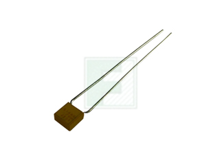
Cap Ceramic 820pF 100V C0G 5% Radial 5.08mm (1%FR) 125°C Bulk
Capacitor,Ceramic,820Pf,100Vdc,.5-Pf Tol,.5 Pf Tol,5-% Tol,5 % Tol,Cg-Tc Code,30Ppm-Tc
CCR05 Series 2.29 x 4.83 x 4.83 mm 820 pF 100 V ±5 % LS=5.08mm Ceramic Capacitor