Panasonic Electric Works HE1AN-W-DC9V-Y7

Mfr.Part #:

HE1AN-W-DC9V-Y7

Manufacturer:

Description:
HE1AN-W-DC9V-Y7 datasheet pdf and Power Relays, Over 2 Amps product details from Panasonic Electric Works stock available at Zeano

RoHS Status:

RoHS

Payment:

Payment

Delivery:

Delivery

Quick Request Quote

Do you want a lower wholesale price? Please send us an inquiry, and we will respond immediately.

Latest Posts

A switch solenoid converts electrical energy into mechanical movement by using a simple principle:...
Voltage controlled oscillator takes a voltage (like from a battery) and turns it into...
Types of computer cables: USB cables, HDMI cables, Ethernet cables, power cables,VGA and display
A potentiometer is like a dimmer switch for electronic devices - it controls the...
Security

Buy With Confidence

ISO 9001
ISO 9001
ISO 45001
ISO 45001
ISO 13485
ISO 13485
ISO 14001
ISO 14001
SMTA
ASA

Specifications

Product Details

Product Comparison

Factory Lead Time
16 Weeks
Contact Material

Contact Material refers to the material used to make the electrical contacts in a component. It determines the electrical conductivity, durability, and resistance to corrosion and wear of the contacts. Common contact materials include copper, silver, gold, and alloys of these metals. The choice of contact material depends on the specific application and the required performance characteristics.

Silver Nickel (AgNi)
Mounting Type

Mounting Type refers to the method by which an electronic component is attached to a printed circuit board (PCB) or other surface. Common mounting types include: * Through-hole: Component leads are inserted into holes in the PCB and soldered on the other side. * Surface-mount: Component is placed on the surface of the PCB and soldered in place. * Press-fit: Component is pressed into place on the PCB without soldering. * Socket: Component is inserted into a socket on the PCB, allowing for easy replacement. The mounting type is determined by factors such as the component's size, shape, and power requirements.

Through Hole
Operating Temperature

Operating Temperature is the range of temperatures at which an electronic component can function properly. It is typically specified in degrees Celsius (°C) and indicates the minimum and maximum temperatures at which the component can operate without experiencing damage or degradation. Operating Temperature is an important parameter to consider when designing electronic circuits, as it ensures that the components will function reliably in the intended operating environment.

-40°C~55°C
Packaging
Tray
Series

Series, in the context of electronic components, refers to the arrangement of components in a circuit. When components are connected in series, they form a single path for current to flow through. The total resistance of a series circuit is the sum of the individual resistances of each component. Series connections are often used to control the flow of current in a circuit, as the total resistance can be adjusted by changing the number or type of components in the series.

HE-N
Part Status

Part Status is an electronic component parameter that indicates the availability and production status of a component. It is typically used to inform customers about the availability of a component, whether it is in production, end-of-life, or obsolete. Part Status can also provide information about any restrictions or limitations on the component's use, such as whether it is only available for certain applications or if it has been discontinued.

Active
Moisture Sensitivity Level (MSL)

Moisture Sensitivity Level (MSL) is a measure of the susceptibility of a surface mount electronic component to moisture-induced damage during soldering. It is classified into six levels, from 1 (least sensitive) to 6 (most sensitive). MSL is determined by the materials used in the component's construction, including the solderability of its terminals and the presence of moisture-absorbing materials. Components with higher MSL ratings require more stringent handling and storage conditions to prevent moisture absorption and subsequent damage during soldering.

1 (Unlimited)
Termination Style

Termination Style refers to the method used to connect an electronic component to a circuit board or other components. It describes the physical form and electrical characteristics of the connection point. Common termination styles include through-hole, surface mount, and press-fit. Through-hole components have leads that are inserted into holes on the circuit board and soldered in place. Surface mount components are soldered directly onto the surface of the circuit board. Press-fit components are inserted into holes on the circuit board and held in place by friction.

PC Pin
Contact Form

Contact Form refers to the physical shape and arrangement of the electrical contacts on an electronic component. It describes how the component connects to other components on a circuit board or other electrical system. Common contact forms include through-hole, surface mount, and pin headers. The contact form determines the method of mounting and soldering the component, as well as its compatibility with different types of circuit boards and connectors.

SPST-NO (1 Form A)
Relay Type
General Purpose
Coil Resistance

Coil Resistance is the electrical resistance of a coil, which is a type of electrical conductor wound into a spiral shape. It measures the opposition to the flow of electric current through the coil. The higher the coil resistance, the more difficult it is for current to flow through it. Coil resistance is typically measured in ohms (Ω) and is an important parameter for determining the electrical characteristics of a coil.

32.4Ohm
Operate Time
30ms
Coil Voltage

Coil Voltage refers to the voltage applied across the coil terminals of an electronic component, such as a relay, solenoid, or inductor. It determines the magnetic field strength generated by the coil and, consequently, the component's operation. Higher coil voltage typically results in a stronger magnetic field and increased force or inductance. The appropriate coil voltage for a specific component is crucial for its intended function and should be carefully selected based on the manufacturer's specifications.

9VDC
Coil Type
Non Latching
Switching Voltage

Switching Voltage is the maximum voltage that a semiconductor switch, such as a transistor or MOSFET, can withstand in the off state without breaking down. It is a critical parameter for power electronics applications, as it determines the maximum voltage that can be applied to the switch without causing damage. The switching voltage is typically specified in volts (V) and is measured between the drain and source terminals of the switch.

480VAC -Max
Coil Current

Coil Current is the amount of electrical current flowing through the coil of an inductor or electromagnet. It is measured in amperes (A) and is directly proportional to the magnetic field strength produced by the coil. The coil current is determined by the voltage applied to the coil and the resistance of the coil.

278mA
Release Time

Release time is the time it takes for a component to return to its original state after being triggered. It is typically measured in milliseconds (ms) or microseconds (µs). A shorter release time indicates that the component can respond more quickly to changes in its input signal. Release time is an important parameter for components such as switches, relays, and transistors.

10ms
Must Operate Voltage
6.75VDC
Contact Rating (Current)
120A
Must Release Voltage
0.45VDC
Seal Rating
Sealed - Flux Protection
Coil Insulation
Class F
RoHS Status
RoHS Compliant
HE1AN-W-DC9V-Y7 Overview
This product is manufactured by Panasonic Electric Works and belongs to the category of Power Relays, Over 2 Amps. The images we provide are for reference only, for detailed product information please see specification sheet HE1AN-W-DC9V-Y7 or the datasheet in PDF format. As a professional electronic components distributor, Zeano has five million electronic components available. Additionally, we have over 500,000 electronic components in stock ready for immediate shipment. If you have requirements, you can send us a quotation form to get the price of HE1AN-W-DC9V-Y7. We attach great importance to our customers' purchasing experience and are willing to establish a long-term cooperative relationship with you. If you have any questions or requirements, please feel free to contact us.
HE1AN-W-DC9V-Y7 More Descriptions
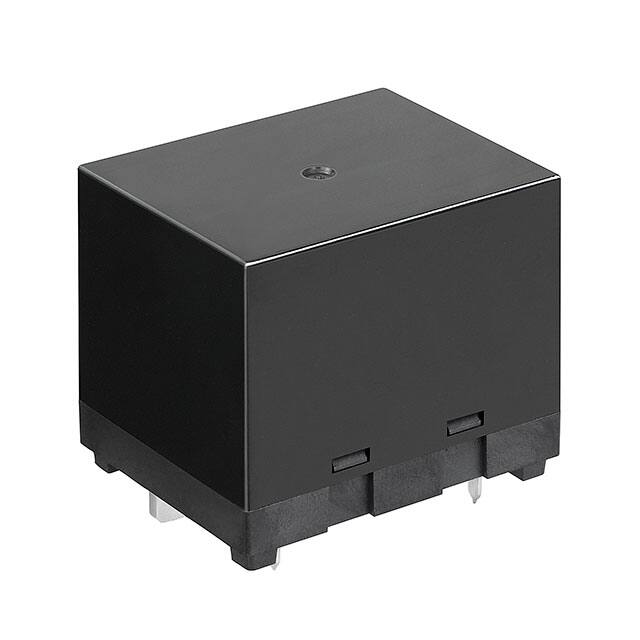
Power Relay SPST-NO 800VAC 9VDC Solder Through Hole Carton
AgNi 9V 120A Normal Open:1A(SPST-Normal Open) Plugin Power Relays ROHS
Power Relay 9VDC 120A SPST-NO(50mm 40mm 43mm) THT
Power Relay 9VDC 120A SPST-NO(50x40x43)mm THT
HE Series SPST 9 V 120 A PV Type Solar Inverter General Purpose Power Relay
POWER RELAY, SPST-NO, 120A, 480VAC, TH;; POWER RELAY, SPST-NO, 120A, 480VAC, TH; Contact Configuration: SPST-NO; Coil Voltage: 9VDC; Contact Current: 120A; Product Range: HE-N Series; Relay Mounting: Through Hole; Coil Type: N
  • Image
    Part Number
    Manufacturer
    Factory Lead Time
    Contact Material
    Mounting Type
    Operating Temperature
    Packaging
    Series
    Part Status
    Moisture Sensitivity Level (MSL)
    Termination Style
    Contact Form
    Relay Type
    Coil Resistance
    Operate Time
    Coil Voltage
    Coil Type
    Switching Voltage
    Coil Current
    Release Time
    Must Operate Voltage
    Contact Rating (Current)
    Must Release Voltage
    Seal Rating
    Coil Insulation
    RoHS Status
    Mount
    Weight
    Published
    Number of Terminations
    Termination
    Packing Method
    Reference Standard
    Body Length or Diameter
    Body Breadth
    Physical Dimension
    Contact Resistance
    Insulation Resistance
    Electrical Life
    Throw Configuration
    Coil Power
    Contact Voltage(AC)-Max
    Contact/Output Supply Type
    Relay Action
    Coil Voltage (DC)
    Coil/Input Supply Type
    PCB Hole Count
    Dielectric Strength Between Open Contacts
    Input Switching Control Type
    Dielectric Strength Between Coil and Contacts
    Contact (AC) Max Power Rating R Load
    Body Height
    Length - Termination
    Number of Pins
    Pbfree Code
    ECCN Code
    Voltage - Rated DC
    Depth
    Voltage - Rated AC
    Max Voltage Rating (AC)
    Max Current Rating
    Max Voltage Rating (DC)
    Contact (AC) Max Rating R Load
    Contact (DC) Max Rating R Load
    Power Consumption
    Length
    Radiation Hardening
    Lead Free
    View Compare
  • HE1AN-W-DC9V-Y7
    HE1AN-W-DC9V-Y7
    16 Weeks
    Silver Nickel (AgNi)
    Through Hole
    -40°C~55°C
    Tray
    HE-N
    Active
    1 (Unlimited)
    PC Pin
    SPST-NO (1 Form A)
    General Purpose
    32.4Ohm
    30ms
    9VDC
    Non Latching
    480VAC -Max
    278mA
    10ms
    6.75VDC
    120A
    0.45VDC
    Sealed - Flux Protection
    Class F
    RoHS Compliant
    -
    -
    -
    -
    -
    -
    -
    -
    -
    -
    -
    -
    -
    -
    -
    -
    -
    -
    -
    -
    -
    -
    -
    -
    -
    -
    -
    -
    -
    -
    -
    -
    -
    -
    -
    -
    -
    -
    -
    -
    -
    -
    -
  • HE1AN-P-DC12V-H18
    12 Weeks
    Silver Tin Oxide (AgSnO)
    Through Hole
    -50°C~55°C
    Bulk
    HE-PV
    Active
    1 (Unlimited)
    PC Pin
    SPST-NO (1 Form A)
    General Purpose
    75Ohm
    30ms
    12VDC
    Non Latching
    250VAC -Max
    160mA
    10ms
    8.4VDC
    35A
    1.2VDC
    -
    -
    RoHS Compliant
    Through Hole
    80g
    2013
    6
    PC Pin
    BOX
    CSA; UL
    38mm
    33 mm
    38mm x 33mm x 36.3mm
    100mOhm
    1000000000Ohm
    30000 Cycle(s)
    SPST
    1.92W
    277V
    AC/DC
    MOMENTARY
    12V
    DC
    6
    2000 Vrms
    Random
    5000 Vrms
    9695VA@277VAC
    36.3mm
    0.004 inch
    -
    -
    -
    -
    -
    -
    -
    -
    -
    -
    -
    -
    -
    -
    -
  • HE1AN-S-DC24V
    12 Weeks
    Silver Tin Oxide (AgSnO)
    Chassis Mount
    -50°C~55°C
    Bulk
    HE
    Active
    1 (Unlimited)
    Screw Terminal
    SPST-NO (1 Form A)
    General Purpose
    300Ohm
    30ms
    24VDC
    Non Latching
    277VAC 30VDC -Max
    80mA
    10ms
    16.8VDC
    -
    2.4VDC
    -
    -
    RoHS Compliant
    Chassis Mount, Flanges
    -
    2003
    -
    Screw
    BOX
    CSA; TUV; UL; VDE
    -
    -
    -
    -
    -
    100000 Cycle(s)
    SPST
    1.92W
    -
    AC/DC
    MOMENTARY
    24V
    DC
    -
    -
    -
    -
    -
    52.8mm
    -
    4
    yes
    EAR99
    30V
    34mm
    277V
    277V
    30A
    30V
    30A@277VAC
    30A@30VDC
    1.92W
    51mm
    No
    Lead Free

Recommended Offers

Melexis Technologies NV
MLX81108KDC-CAE-000-SP
Maxim Integrated
MAX3079EEPD+
Vishay Siliconix
DG613AEN-T1-E4
Vishay Siliconix
DG613AEY-T1-E3
Vishay Siliconix
DG611AEY-T1-E3
Nexperia USA Inc.
74HCT4852D,112
Vishay Siliconix
DG2032DN-T1-E4
ON Semiconductor
NLAS4717MR2G
Vishay Siliconix
DG2020DV-T1-E3
NJR Corporation/NJRC
NJU4053BM
Vishay Siliconix
DG611AEQ-T1-E3
Nexperia USA Inc.
74LV4053DB,112